Basement Woodshop Tour

January 25th, 2009 7 comments

This is a 10 minute video tour of my basement woodworking shop.
I think I’ve gotten my shop off to a good start, but it still has a long way to go.

I have good tools, in the good locations, good lighting, electricity from the ceiling to keep the floor clear, and good dust collection.
The next stage is to build some good shop cabinetry and a workbench.

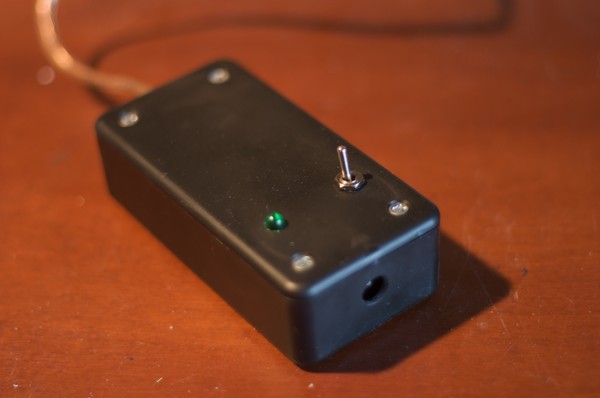
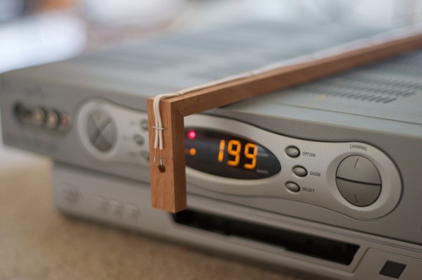
This video is a review of a steadicam where I shoot a cool video of my basement workshop.

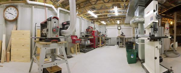
Here is a panoramic shot of from the middle of the shop.

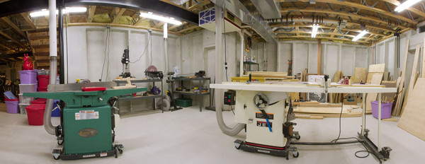
Another pano showcasing my jointer and tablesaw.

A pano of my miscellaneous workbench area.

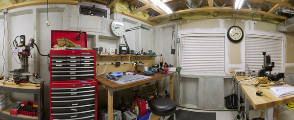
My workshop computer is in the foreground.
The 2 garden basement windows are the main way I get large rough lumber into my basement.
You can see my facination with old clocks on the walls.
I am also interested in CNC milling among other things.

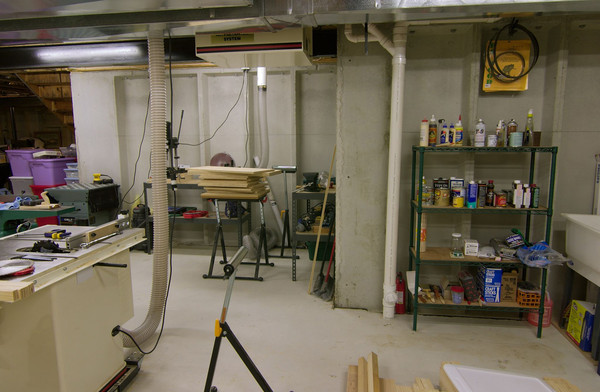
This is the main woodworking area of my shop.
You can see the air compressor line on the ceiling.
The air compressor is on the opposite side of the basement.

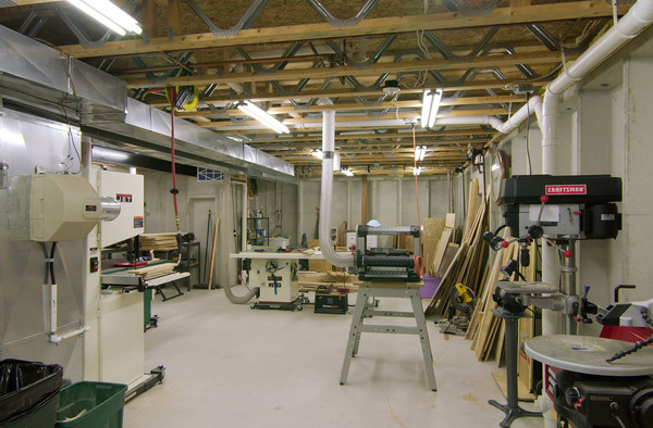
From the rear of the shop.

The back area of the basement.
I need to build an outfeed table / workbench at the back of the tablesaw here.
I store my stains, glues, shellacs and whatnot here near the basement sink.

Microprocessor Controlled Solar Tracking Device

July 15th, 2008 3 comments

Light sensitive tracking device. This was a really fun college project.
This is an excerpt from my project log book.

Download pdf of project log book.

I put the circuitry on 2 seperate boards with a connecting data ribbon.
1 board was the computer processor and the other was the I/O board.
That way, I could re-use the processor board for future projects.

The potentiometer adjusts the photosensor sensitivity.

The project was based on the 8085 microprocessor.

I used a stepper motor to control rotation of the parabolic reflector.
The reflector was actually a solar cigarette lighter from radio shack.
I attached 2 photosensors side by side on the reflector focal point.

More wire-wrapping technique, same as the digital oscilloscope project.

The electric motor is a 1.8 degree/step 12v stepper motor.

I entered this project into the 1987 DeVry Career Expo (Irving, TX) and won second place.
I didn’t sleep the last 48 hours before the competition and finally got it working just 10 minutes before the expo opened.

Categories: Gadget Tags:

3D Visualization of Broken Arm

July 4th, 2008 Comments off

On september 16 of 2007, I took a ride on my 1982 yamaha seca 400 … I had just synced the carbs and the bike was runnin good… so good.. it caught me by surprise.  As I went through an s turn, the bike accelerated better than expected.  It was dark and my headlight was angled too low, which gave me little time to see the back side of the s-curve.  I hit the brakes and skidded into the curb which dumped me into the grassy median.  I would guess I was going 35 mph when I hit.  As I fell, my left hand instinctively tried to catch my fall.  Bad idea, because I heard my forearm shatter like a tree branch snapping, then I rolled 1 time onto my right shoulder (fracturing it).  I’ve been riding since 82 and this is my first accident.

Categories: Computer Tags: , , ,

Infrared (IR) Remote Extender

April 6th, 2008 11 comments

This circuit can be used to operate a DVR cable box from another room. It’s really an infrared signal repeater. The signal from the remote is received and then retransmitted over wires to an infrared LED. The beam from the LED is then picked up by the receiving window of the cable box.

The visible light LED in series with the IR transmitter is used to indicate that an IR signal has been detected. The 100k potentiometer adjusts the repeater’s sensitivity.

I bread boarded the circuit first to make sure it would work.
I learned that the remote needed to be withing 1 foot of the IR reciever to work.  This was sufficient for my purpose.  If you need greater range, then you’ll need a more complex circuit (see google).

I put the circuit into a case and solder the components onto a small circuit board.
I added a switch and a 9 volt battery.

Here is the completed case.  You can see the hole for the IR receiver on the end of the box.  If you will be using this device in a room with many sources of light, you should put an IR filter in front of your IR receiver.

I concocted this wooden arm to hold the IR transmitter in front of my cable box.

Categories: Gadget Tags: