Archive for 2007

Digital Oscilloscope

December 17th, 2007 No comments

Digital oscilloscope project created with wirewrapped microprocessor and hand build LED array.

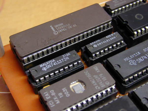
This is a digital oscilloscope that I built in 1987 in college.  It is based on the early generation 8088 CPU.

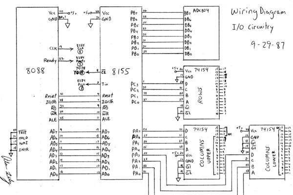
This is an excerpt from my project log book.  My professor made us keep a log book of project design, circuit diagrams, and source code.  

Download project log book (pdf file)

Partial circuit diagram from log book.

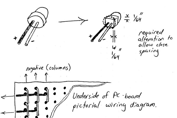
I tediously built the 28×16 digital led display.

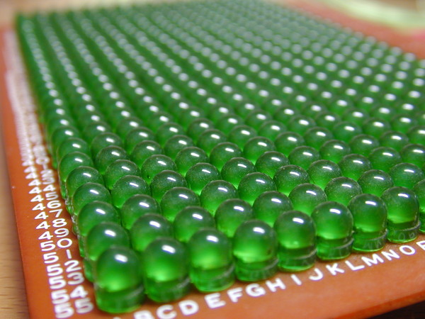
I had to melt each side of every LED so that the would fit close together.

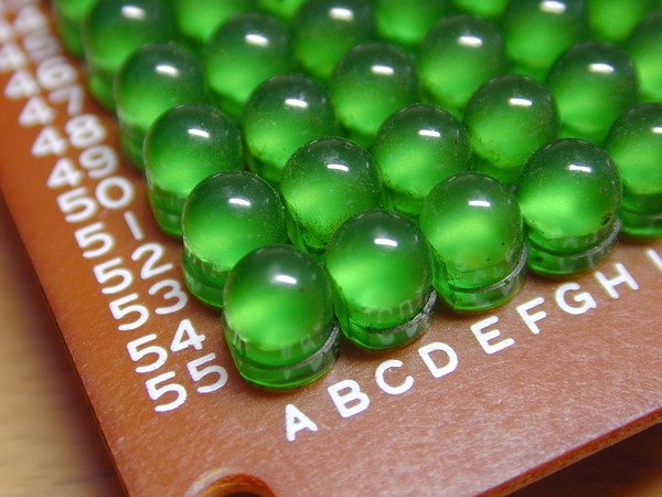
448 LEDs soldered into a XY grid.

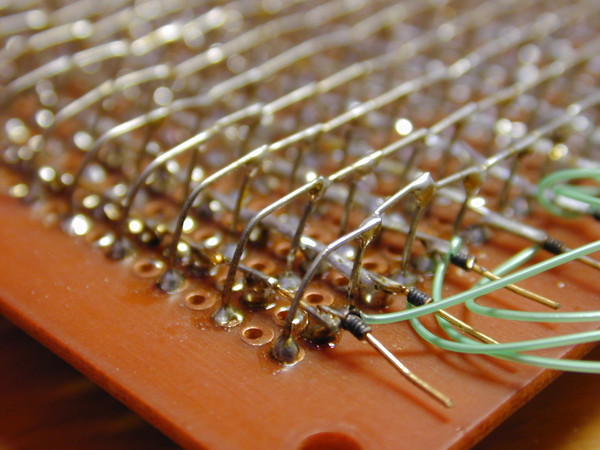
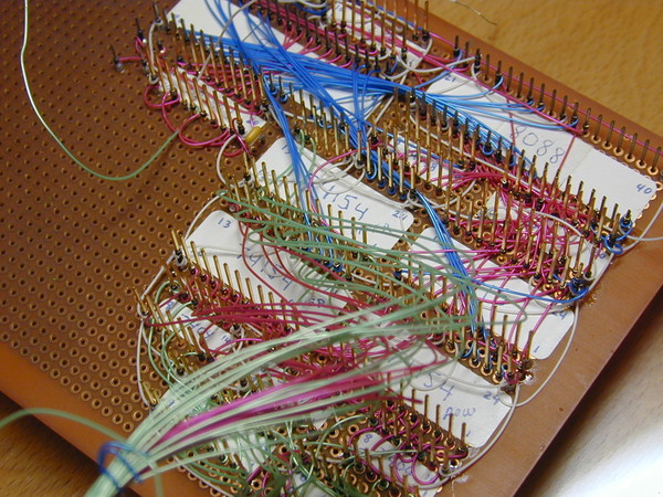
It takes a lot of wirewrapping to connect all of the circuitry.  This was the industry technique for prototyping electronic circuits in the 80’s.

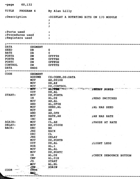
This is an early test program (assembly source code), which was stored on the erasable programmable memory chip (EEPROM).  Assembler programming is just 1 step above programming at the binary level.

Categories: DIY Tags:

2007 Triumph Thruxton

November 11th, 2007 1 comment

2007 Triumph thruxton.  Is she cool or what?  Black is the fastest color, ya know.  This is a cold start, on a cold day, so it took a minute to warm up.

I hated the redesign of the 2008 model where they got rid of the clip-on style handlebars, so I had to get the last 2007 model from my local triumph dealer. I am very satisfied with my decision. I had the dealer add the predator exhaust, AI kit, flyscreen, knee pads, and bar end mirrors.

The top reasons I chose the triumph thruxton over the ducati sport 1000:

- price, including maintenance costs
- I didn’t like the ducati vibration at low rpm
- the thruxton is plenty fast enough, but the duc was scary fast
- the retro thruxton was just cooler lookin for my taste
- sounds great with british customs predator exhaust
- more devoted fan base and mod options for the thruxton

Engine closeup.  2007-2008 are the last years of the old-school carbureuter on the triumph thruxton.  From late 2008, the carb is actually electronic fuel injection inside a fake carb body.

Categories: DIY Tags:

1982 Yamaha Seca 400

August 25th, 2007 3 comments

Here is a video of me riding my Seca.  Keep in mind that I am 6′ 2″ and my long legs make this bike seem smaller than it is.

1982 Yamaha Seca 400cc – 19800 miles

This was my second motorcycle.  I bought it in college after my honda mb5 50cc bike was stolen.  This yamaha seca cost me $1200 in 1984.  The dealer sold it as new old stock.  It was originally a more beautiful candy apple red, but it sat in the Florida sun for a couple years and I had to repaint it.  This color is ferrari red.  She cleaned up nice.  The boxy gauges were the popular style in 1982.

I sold it after I had bought my 2007 triumph thruxton.

The dual megaphone exhausts sound sweet.

Everything is original except the horn.  I replaced that the first year I had the bike.

This motorcycle looks very unique on the road compared to most modern bikes.

Engine is solid, runs smooth, and purrs like a kitten.
It’s always been cold blooded… so it requires a little choking for a cold start and a short warm up period.

Categories: DIY Tags:

How to Replace a 98 VW Golf Front Bearing

July 7th, 2007 24 comments

My 1998 Volkswagen Golf GTI VR6 has been an awesome car, but things are starting to fail after 150,000 miles.  This is the procedure I went through to replace the right front bearing recently.  The left front bearing died at 130,000 miles.

It is important to know whether your vehicle has a PLUS SUSPENSION. My 98 VW GOLF GTI is a “special edition” model which came with this. You will not be able to remove the hub on a VW with PLUS SUSPENSION without a hub puller AND you will not be able to reinstall the hub without the axle puller tool. The axle/hub splines are compressed on the PLUS SUSPENSION to eliminate backlash.

I don’t know how many VW’s have a PLUS SUSPENSION, but I guess it is not as common. The intent of the compressed splines was to completely eliminate backlash.

I needed a few specialized tools to replace the bearing.  You gotta have the right tools for the job.

This tool is a tie rod ball joint separator.

My new favorite tool… the air impact wrench.  My old one had 165 ft. lbs of torque.  I can’t believe I hesitated when buying this one with 585 ft. lbs of torque.  It saves a lot of time and headache.

A quality grease is very useful.

An impact screw driver is a must for stubborn screws.  Otherwise you will just strip them.

Drive axle hub press (modified).  I didn’t want to pay for the expensive VW tool, so I bought this generic model and I had to modify the bolts with special washers and standoff sleeves.

Axle puller.
When you are reinstalling the hub… this tool helps pull the hub back onto the splined axle.
You thread the inner part onto the axle and you tighten the silver nut which pushes on the loose outer cylinder of the tool.. which presses against the hub.

Hub puller.

6 ton bench press.  Got this at harbor freight for $60.

This completes the list of special tools needed to replace the front bearings on my golf.  Of course, you’ll also need lots of wrenches, sockets, and typical garage tools as well.

If you don’t have all of these special tools, don’t even attempt to replace your VW golf front bearings.

First thing after jacking up and removing the front tire… is to press the hydraulic brake caliper piston back enough so that you can easily remove the caliper assembly.  I use a bolt and a screw driver at this location as a lever.

2 bolts hold the caliper to the wheel knuckle.

This bucket is the perfect height so I can rest the caliper without putting unnecessary stress on the rubber brake line.

Now remove the single screw that holds the brake disc to the hub.

Disconnect the ABS brake sensor.

In order to loosen the axle nut… you need to put the wheel back on and lower the tire, so that the torque stress imposed on the nut is not transferred to your transmission.

It’s important to keep your nuts and bolts organized.

Now you can pull the hub off the axle.  I greased the tool threads and tool tip and things went much smoother.

Here you can see the hub with part of the bearing stuck to it.  (I remove it later).

Here is a diagram of how the hub puller works to pull the hub off the axle shaft.
As the hub puller bolt is tightened, it is pushing on the axle shaft while simultaneously pulling the hub off the axle shaft.

Unbolt the tie rod end.  If you attempt to use a hand wrench the bolt may spin with the nut.  A powerful impact wrench will save you some headache.

Use this special tool to press the tie rod end bolt off.

The bottom of the knuckle is attached to the lower ball joint which is attached to the arm by 3 bolts.  I used the angle impact wrench to remove these.

You need to compress the spring before you can remove the knuckle assembly.  This spring compressor was cheap from harbor freight.  I had to modify it so I could invert them by welding the nuts on the end of the screw.  That way, I can quickly compress the spring with a power tool.

Removing these nuts normally took a lot of effort before I got my new impact wrench.

Remove the brake dust cover.  The 3 bolts are 8mm.

Remove the mangled outer plastic liner from the outer bearing race that is stuck to the hub.

Remove the ring clip on the one side of the bearing.  I had to modify these needle nose pliers by curving the tips inward slightly so they could grip the ring clip.

Place the knuckle face down on the hydraulic press.  I used to blocks of ash wood to allow space for the old bearing to fall out.  Harbor freight sells a cheap set of differently sized arbors for pressing out bearings.  You need to push across the entire surface of the bearing, not just the center.

The tie rod arm needs to be raised about 1/8″ on one side so the knuckle lies perfectly flat.

Remove the ABS sensor ring from the hub.

It took a bit of engineering to remove the partial bearing from the hub.

I used a puller with the jaws ground to a sharp edge because the lip is very small.
The puller needs something to push against, so I placed a small arbor on top of the hub.

This is what a bad bearing looks like close-up.
I don’t think a good bearing should have ANY rust.

I placed the knuckle on a block of ash with the outer side facing up.
The bearing should be pressed-in with the writing facing up.
I had to cut a large washer to match the size of the bearing because I don’t want to damage the bearing when I press it into the knuckle.

The bearing is already pressed into place in this photo, but you can see how the washer fit over the bearing and the arbor was between the washer and the press rod.

Put a new ring clip in to hold the bearing in place.

IMPORTANT: Don’t forget to put the ABS sensor ring back on before pressing the hub into the new bearing (THAT WOULD SUCK!).

Place the hub upside down in the press so I can press the bearing onto the hub.

Another tight fitting washer/arbor to evenly distribute the pressure on the new bearing.

This is what the hub looks like after pressing the bearing onto it.

Time to reassemble.  You need to use the axle puller to get the hub back on the axle.

Thread the axle nut to 148 ft. lbs.
Then reverse 1 turn.
Then tighten to 37 ft. lbs.
Then tighten an additional 30 degrees.  (each point on the 12 point nut is 30 degrees)

Everything else is just the reverse of the uninstall process.

This fixed the bearing problem, but now I can clearly hear the ball joint popping… so I have to replace the ball joint.  I wish I had replaced the ball joint while replacing the bearing, it would have been easier.

Categories: DIY Tags: